
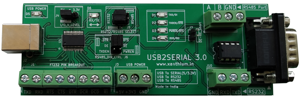
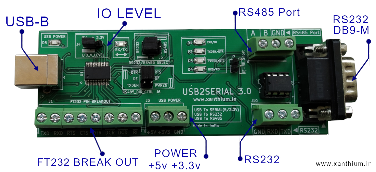
USB2SERIAL V3.0 is an easy to use
- USB to Serial Converter with selectable 3.3V and 5V logic levels
- USB to RS232 Converter
- USB to RS485 Converter
- FT232RL USB to Serial breakout board with screw terminal block Connectors
You can buy USB2SERIAL from here.
Contents
- Required Device driver
- Circuit Diagram
- Connecting USB2SERIAL on Windows
- Connecting USB2SERIAL on Linux
- Serial Permissions on Linux USB section
- RS232 Section
- RS485 Section
- Indicator LED's
- Power Connectors
Device Driver Software

- USB2SERIAL V3.0 uses FT232 chip from FTDI at the USB end.
- The VCP drivers for FTDI FT232RL can be downloaded from here.
- Most Linux versions already have the FT232 drivers in the kernel so the device will work without installing any drivers.
Circuit Diagram
Connecting USB2SERIAL on Windows
- Please make sure that VCP drivers for FT232 are installed .
- Once you connect the device to USB port of a Windows machine, the OS recognizes the device and show it as a Virtual COM Port in Device Manager.
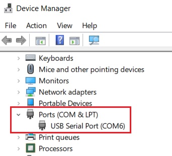
You can then read and write to the device.
Connecting USB2SERIAL on Linux distributions.
On Linux distributions,
- Connect USB2SERIAL V3.0 to the USB port .
- The D6 (RX/TX) LED will blink as the device is detected by the OS.
- Now open the Linux terminal and type the following command sudo dmesg | tail and press enter.
sudo dmesg | tail 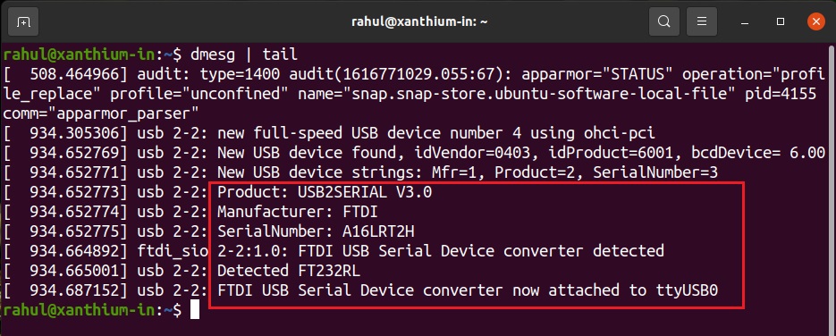
The above image shows that OS (Ubuntu) has detected the device and assigned the name ttyUSB0.
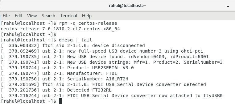
USB2SERIAL V3.0 getting detected in Centos 7 (above)
- You can now use ttyUSB0 as the port name to communicate with the device.
- Please note that there will be small changes in the port name depending upon your Linux version.
Serial Port Permissions under Linux
On most Linux system access to serial ports (USB based Virtual Serial Port or Hardware Ports) are restricted due to security reasons.
If you tried to access the serial port you will get a ttyUSB0 or ttyACM0 access denied error.
On Linux to access the serial port the user must be part of 2 groups
- tty
- dialout
You should add yourself to these two groups using the usermod command.
sudo usermod -a -G tty username
sudo usermod -a -G dialout username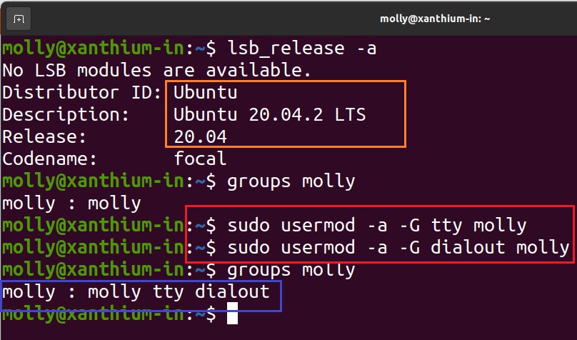
Eg: Adding the user molly to dialout and tty groups on Ubuntu 20.04 LTS (Debian based)
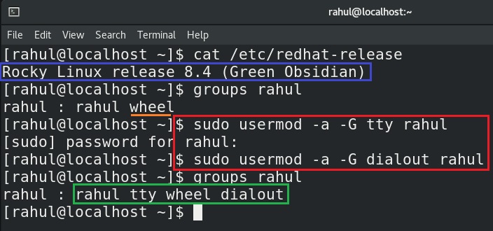
- Adding the user rahul to dialout and tty groups on Rocky Linux (Centos/RHEL/Fedora derivative)
- Make sure to Log off after running the commands.
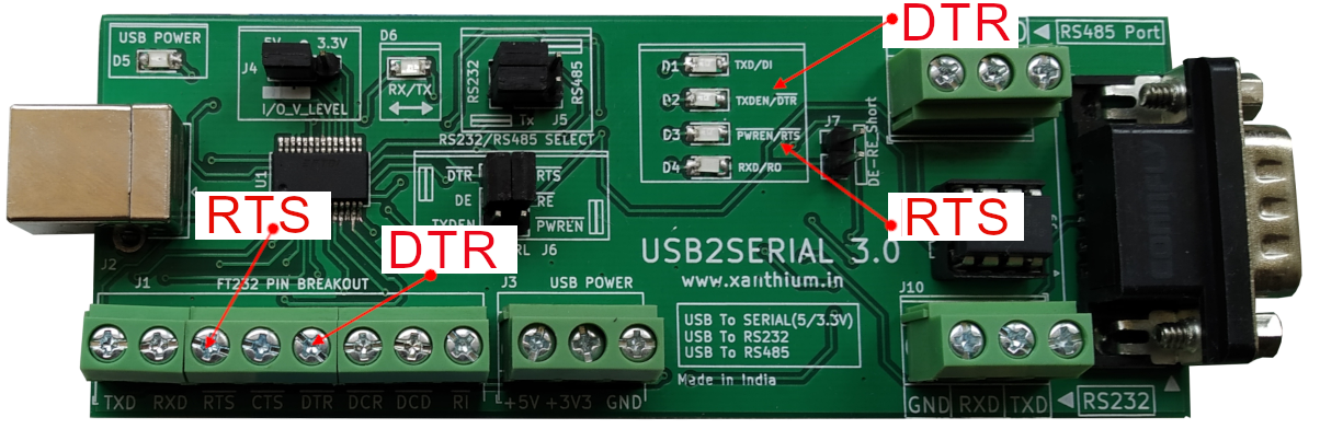
USB section
Here we will talk about the USB section of USB2SERIAL .Circuit shown below.
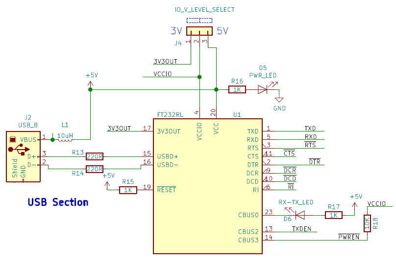
USB section of USB2SERIAL is based on the popular FT232 USB to serial converter ic from FTDI. 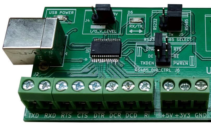
All the pins of FT232 belonging to the serial protocol TXD,RXD,RTS,CTS,DTR,DCR,DCD,RI are bought outside to terminal block connector J1 for easy access.
The board acts as a FT232 break out board with screw terminals in this regard.
Board is also capable of providing extra 5V and 3.3V output.
RTS,CTS,DTR,DCR,DCD and RI are inverted (Active LOW signals).Please take that into account while programming the RTS and DTR Pins of FT232.Setting the pins (RTS/DTR) HIGH in software would result in logic LOW (0V) on the pin and Vice versa.
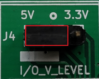
The board also let the user to choose between 5V and 3.3V logic level voltages for the FT232 pins for interfacing with both 5V and 3.3V logic families. Voltage selection is done using the jumper J4 as shown above
D6 LED is used to indicate the transmission or reception of bytes through the FT232RL.
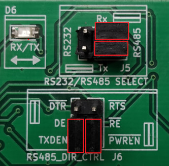
RS232 Section
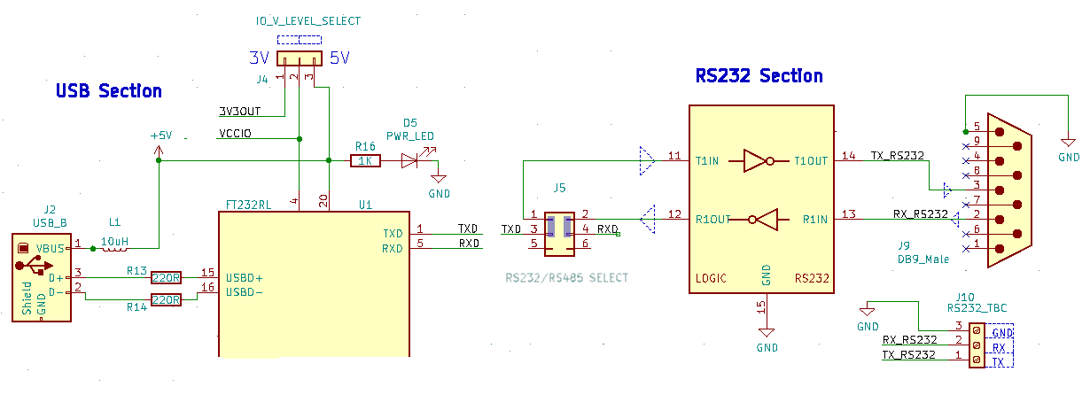
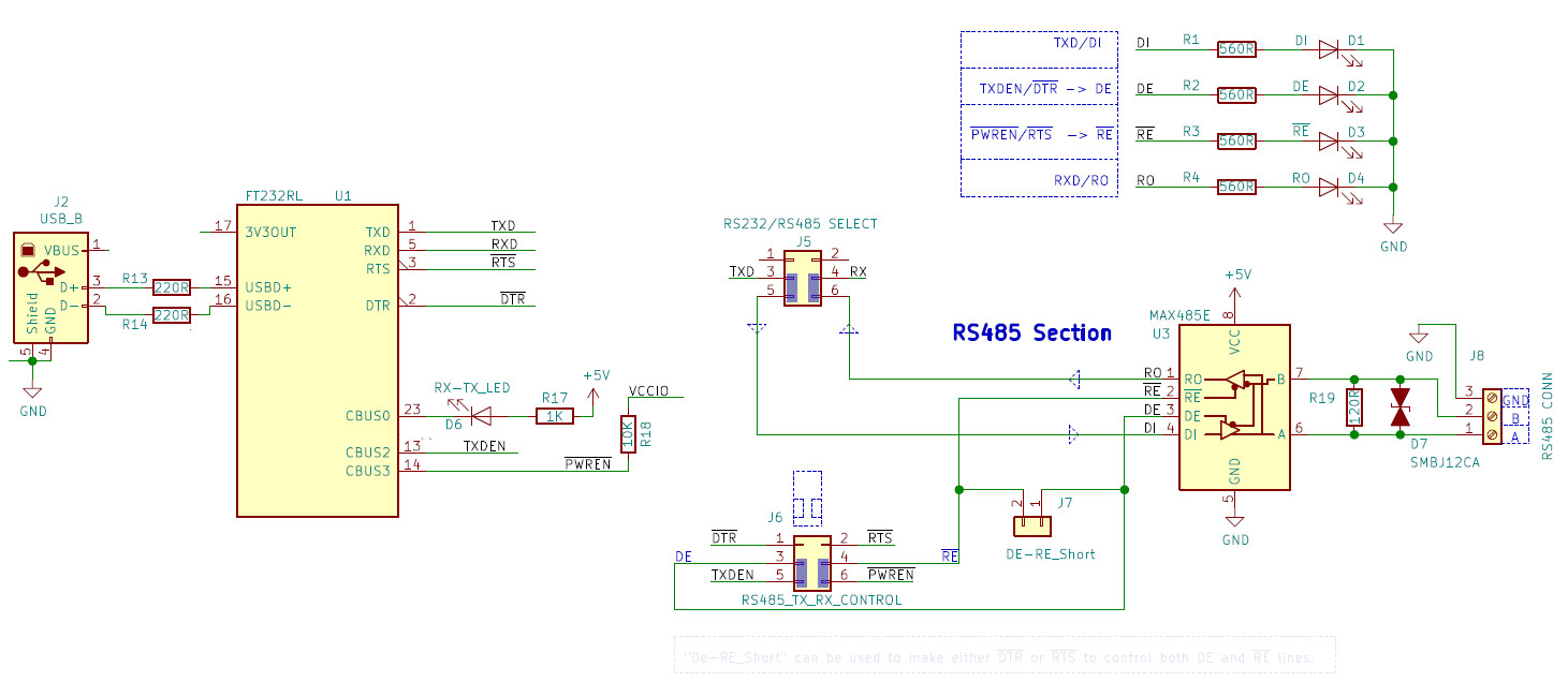
The above image shows the circuit diagram of USB2SERIAL operating as a USB to RS232 converter.
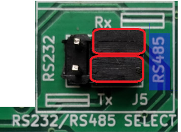
The blue rectangle(above circuit diagram) on J5 represents the jumpers used for selecting the RS232 mode.
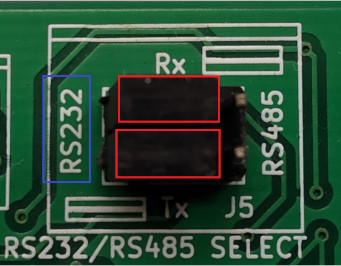
Move both the jumpers on J5 towards the RS232 label as shown in the above image.
This connects both TX and RX to the RS232 converter chip.
USB2SERIAL V3.0 provides both DB9 male Serial port connector as well as a 3 pin TBC connector for the RS232 level signals.
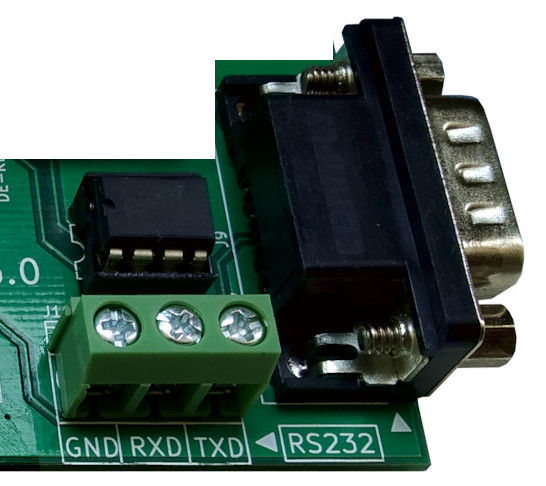
- Please note that only signals RXD,TXD and Ground are available with RS232 voltage levels.
RS485 Section
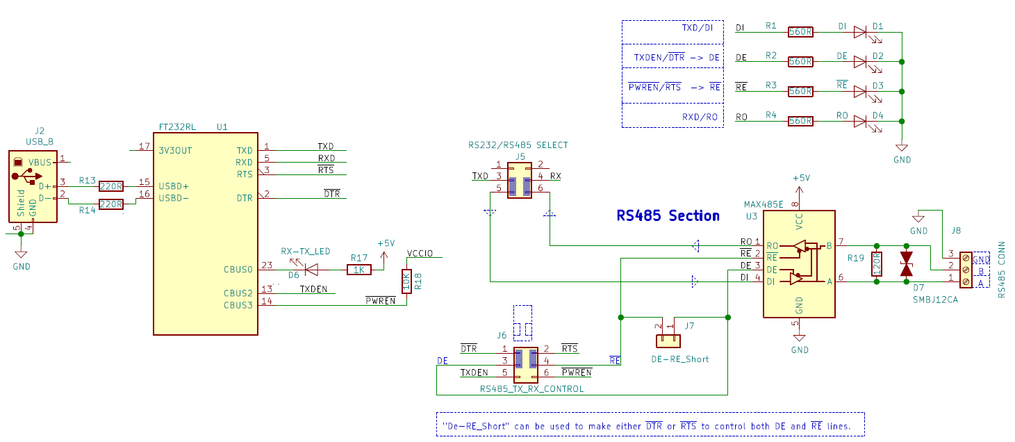
The USB2SERIAL can act as a USB to RS485 converter for communicating in industrial environments and comes with a 3 PIN TBC RS485 port (A,B,GND).
The RS485 mode is selected by moving the jumpers on J5 towards RS485 label as show in the above figure.
This will connect the
- TXD pin to DI of RS 485 chip
- and RXD to RO pin of the RS485 Chip.
The direction of transmission is controlled by the ~RE (active low) and DE pin of the MAX485 chip.Do refer the above circuit.
The connector J6 is used to select between the different modes.
The USB2SERIAL provides the following methods to control the direction of RS485 communication.
- using ~DTR and ~RTS pins of FT232RL (default)
- using CBUS2 and CBUS3 pins of FT232RL (FTDI datasheet method)
- by using only ~RTS pin of FT232RL
- by using only ~DTR pin of FT232RL
~DTR and ~RTS based direction control
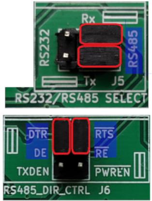
In this mode, the pins ~RTS and ~DTR (active low) are used to control the direction of RS485 transmission. The above figure shows the jumper settings of this mode .
This is the default mode used by USB2SERIAL and all the PC side RS485 communication software available on our site uses this method.
The software uses the serial port API's available in C# and Python to set and clear the RTS or DTR pins of FT232 which in turn controls the ~RE and DE pins of MAX485.

Using CBUS2 and CBUS3 pins of FT232RL
In this method,CBUS2 and CBUS3 pins are used to control the direction pins of MAX485.The jumper settings for this mode can be seen above.
With RS485, the transmitter is only enabled when a character is being transmitted from the UART. The TXDEN signal CBUS pin option on the FT232R is provided for exactly this purpose and so the transmitter enable is wired to CBUS2 which has been configured as TXDEN.
Similarly,CBUS3 has been configured as ~PWREN. This signal is used to control the MAX485's receiver enable. The receiver enable is active low, so it is wired to the ~PWREN pin to disable the receiver when in USB suspend mode.
CBUS2 = TXDEN and CBUS3 = ~PWREN are the default device configurations of the FT232R pins.
The circuit diagram of this mode is below (click to enlarge).
Using only ~RTS or ~DTR pin
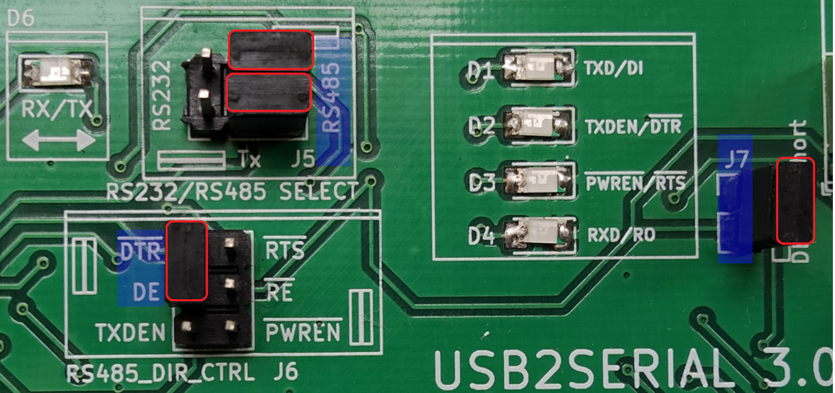
In this mode ,only a single pin either RTS or DTR is used to control both the direction pins of the MAX485.The jumper settings (for DTR only control) can be seen above.
Here ~DTR pin is connected to DE and jumper J7 is shorted.
This shorts DE line with ~RE which connects to the DTR pin. So when ~DTR line is HIGH,DE is Enabled and ~RE(active low) is disabled.
Circuit diagram along with jumper settings is shown below (click to enlarge).
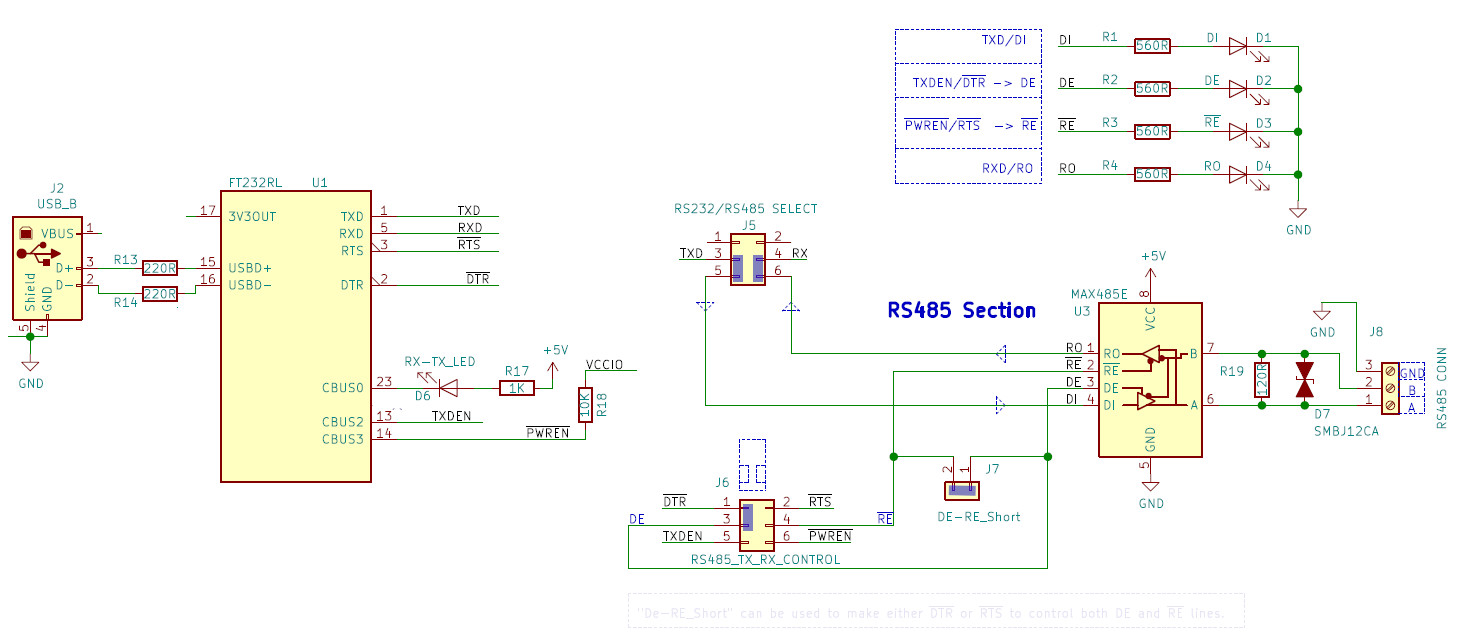
For using only ~RTS pin just connect ~RTS to ~RE .
Indicator LED's
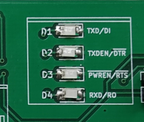
The USB2SERIAL comes with a handy set of 4 LED's that indicate the status of all 4 RS485 pins (data IO and Direction control).
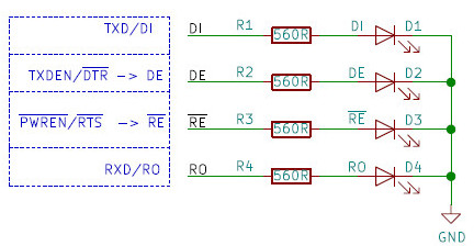
This makes it quite easy for the user to develop and debug RS485 communication programs.
Power Supply
USB2SERIAL is capable of providing power to external circuits through connector J3 (USB POWER) .
All the power is sourced from the PC's USB port and is subjected to limitations of the USB port.
The Connector provides
- +5V
- +3.3V
- Ground
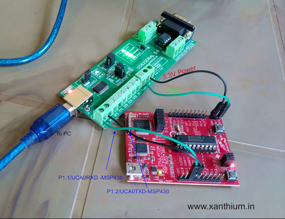
The 3.3V is usefull for powering 3.3V tolerant Microcontrollers as Shown below.
USB2SERIAL V3.0 providing power to MSP430G2553 on Launchpad.
Back to USB2SERIAL Product Page