
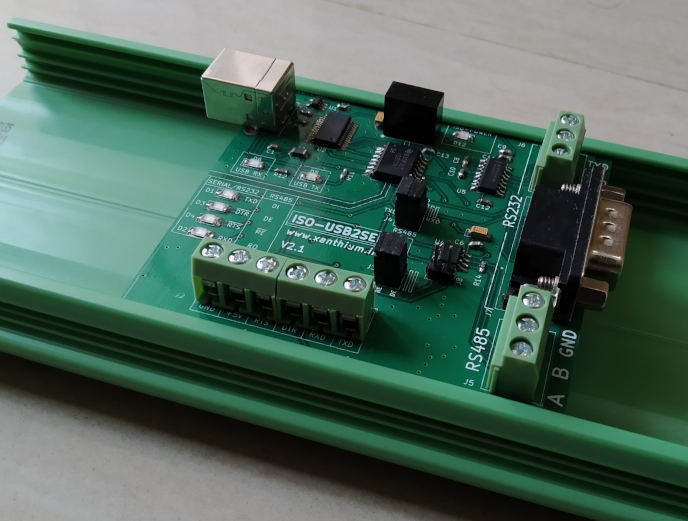
ISO-USB2SERIAL V2.1 is an industrial grade ,DIN rail mountable USB to Serial /RS232/RS485 converter.
Device Driver Software

- ISO-USB2SERIAL V2.1 uses FT232 chip from FTDI at the end.
- The VCP drivers for FTDI FT232RL can be downloaded from here.
- Most Linux versions already have the FT232 drivers in the kernel so the device will work without installing any drivers.
Connecting ISO-USB2SERIAL on Windows
- Please make sure that VCP drivers for FT232 are installed .
- Once you connect the device to USB port of a Windows machine, the OS recognizes the device and show it as a Virtual COM Port in Device Manager.
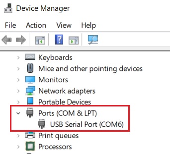
You can then read and write to the device.
Connecting ISO-USB2SERIAL on Linux distributions.
On Linux distributions,
- Connect ISO-USB2SERIAL to the USB port .
- The D6/D5 (RX/TX) LED will blink as the device is detected by the OS.
- Now open the Linux terminal and type the following command sudo dmesg | tail and press enter.
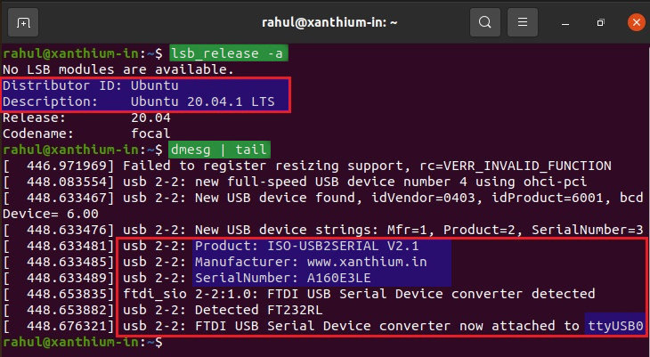
- The above image shows that OS (Ubuntu) has detected the device and assigned the name ttyUSB0.
- You can now use ttyUSB0 as the port name to communicate with the device.
- Please note that there will be small changes in the port name depending upon your Linux version.
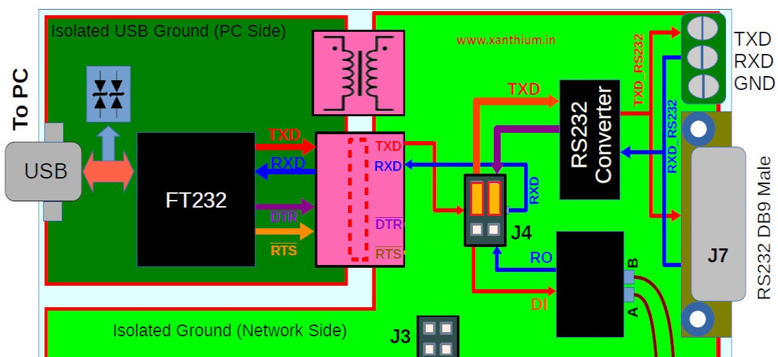
Block Diagram of ISO-USB2SERIAL
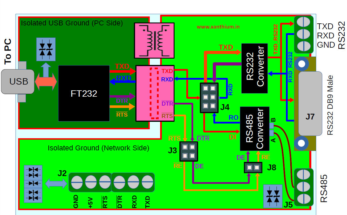
The above figure shows the block diagram of the ISO-USB2SERIAL.
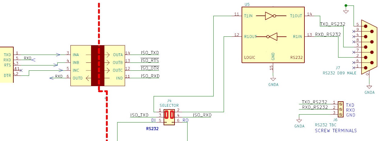
Circuit Diagram
The below image shows the simplified circuit diagram of the Isolated USB to Serial/RS232/RS485 Converter.
Please note that the isolated power supply is not shown in the circuit below.
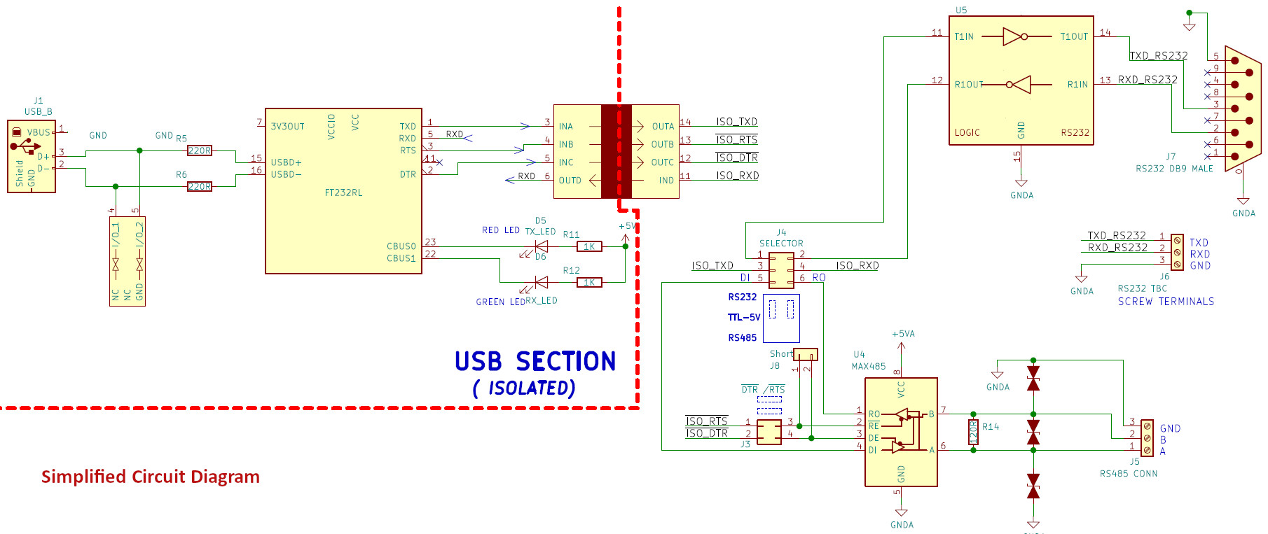
Click the image to enlarge.
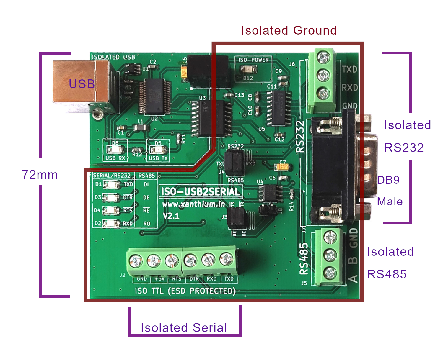
- The USB section consists of FT232RL chip for stable and universal compatibility on all 3 platforms Windows (Windows 10,Linux and Mac OSX).
- The USB section uses the USB type B connector as it is easier to connect with standard printer cable and is more resistant to dust and easy to clean in an industrial environment.
The RS232 and RS485 section are isolated from the USB section using an Isolator chip and an Isolation transformer. The device comes with robust isolation barrier of about 5000 VRMS isolation ratings per UL 1577.
Isolated Serial Port (5V TTL Signal Levels)
- Isolated TXD,RXD,~DTR and ~RTS signals are available on terminal block J2 along with isolated 5V and GND pins.
- ~DTR and ~RTS pins are active low signals.
- The isolated signals available on J2 are 5V TTL outputs.
- The user can source a current of about 150mA from the +5V and GND pin of J2 for powering external devices.
All the pins are protected using TVS diodes along with series resistors (560 R) on signal pins as shown below.
isolated serial ttl outputs of iso-usb2serial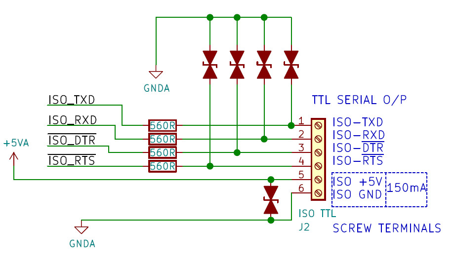
Isolated RS232 Serial port
The RS232 section converts the 3 signals RXD,TXD and Ground to EIA232 levels using a standard converter .The RS232 output is available as a standard DB9 Male connector (J7) or a 3 Pin Terminal Block Connector (J6)
The board is capable of supporting bit rates for upto 250 kbit/s
ESD Protection for RS-232 Bus Pins
- ±15-kV Human-Body Model (HBM)
- ±8-kV IEC61000-4-2, Contact Discharge
- ±15-kV IEC61000-4-2, Air-Gap Discharge
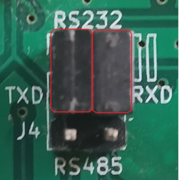
Selecting the RS232 Mode.
The ISO-USB2SERIAL can be put into the RS232 mode by moving the two jumpers (highlighted in orange) of J4 to the RS232 position as shown below.
This would connect the RXD and TXD lines coming from the FT232 to the RS232 level shifter IC. Please note that only RXD and TXD are level shifted.
Isolated RS485 Port
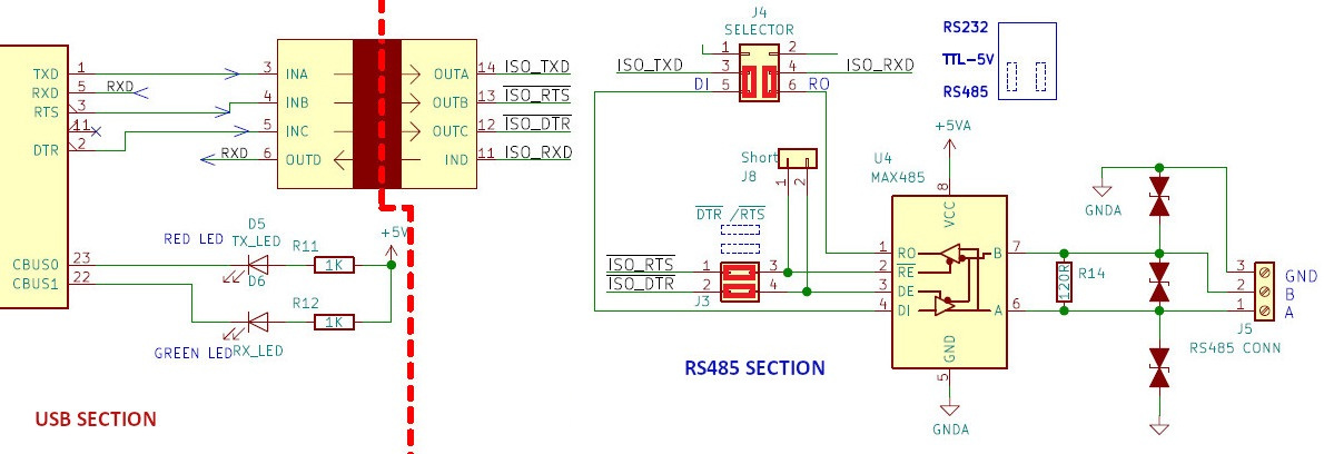
- In the RS485 mode ,RX and TX of the FT232 are connected to the RO and DI pins of the RS485 transceiver chip.
- The ~RTS and ~DTR pins of the FT232 are connected to the ~RE and DE pins of the MAX 485 chip and is used for controlling the direction of transmission.
- In order to put the ISO-USB2SERIAL into the RS485 mode ,move the two jumpers on the connector J4 to the RS485 mode as shown in the below image .
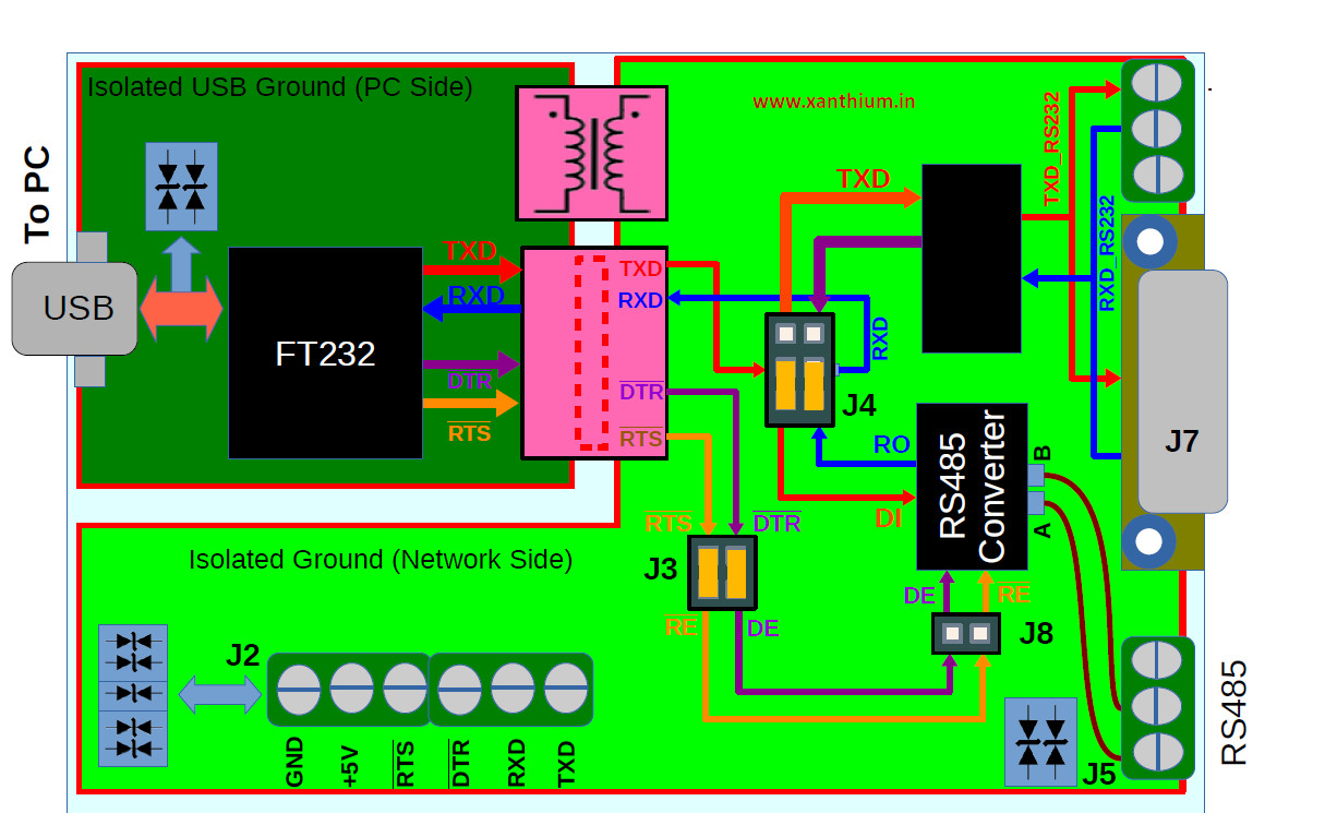
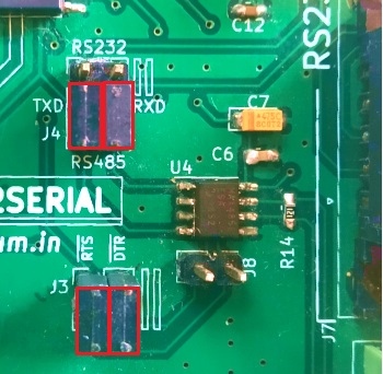
this will make the connections as shown in the below circuit.
- Here ~RTS and ~DTR are used to control the direction of transmission.
- You can use any programming language API to control the signal levels of ~RTS and ~DTR pins to control the direction of RS485 transmission.
- Making ~RTS HIGH using a programming language API would result in ~RE being LOW since the signals are inverted, thus putting the MAX485 chip in receive mode and vice versa .
In the programming language examples provided ,both RTS and DTR pins are used to set the direction of transmission.
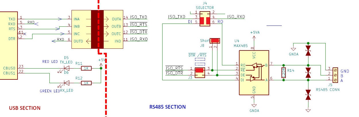
The ISO-USB2SERIAL also let you control the RS485 direction using either ~RTS or ~DTR. For that you have to take the jumper from J3 and short J8.
For eg ,If your program uses only the RTS pin to control the direction of RS485 transmission.
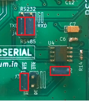
Remove the DTR jumper from J3 and use it to short the J8 as shown below. This would result in RTS line getting connected to both ~RE and DE pins of MAX485 chip as shown below.
Tags
- Log in to post comments