
In this tutorial, we will learn to configure an ATmega328P microcontroller to work with an external Quartz Crystal operating at 11.0592MHz or any other frequency of your choice.
ATmega328P is a widely used microcontroller developed by ATMEL Corporation(Now Microchip).It is used in the popular Arduino platform (Arduino UNO).
If you have a freshly purchased ATmega328P from the factory, By default the AVR CPU will source its clock from the Calibrated internal RC Oscillator which runs at 8MHz.
This 8MHz Clock is divided by 8 by an internal clock prescaler making the effective clock rate to the CPU = 1MHz
Sometimes we may need to source the clock from an external Quartz crystal to run the ATmega328P at a higher speed or have good temperature stability. For using the external clock source, we have to program the internal Fuse Bytes of the ATmega328P.
Please note that incorrect values in the Fuse Bytes will result in your Microcontroller being locked out.
Make sure that an External Crystal is attached to your Microcontroller before trying this.
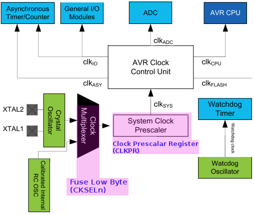
Basic Clock System of ATmega328P
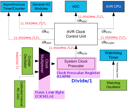
Here is a brief overview of the internal clock system of the ATmega328P Microcontroller.
ATmega328P can be clocked by 6 options as shown below.
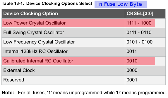
We are interested in the following clocking options only.
- Calibrated Internal RC Oscillator (Default Clock Source)
- Low Power Crystal Oscillator (Quartz Crystal Source)
By default,
ATmega328p is clocked by the Calibrated internal RC Oscillator which runs at 8MHz.The 8 MHz clock is divided by 8 due to the setting of the CKDIV8 bit in Fuse Low Byte.So effective clock rate available is 1 MHz.
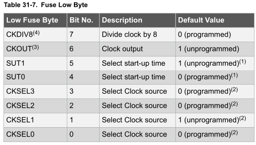
To Configure the Micro controller to use the External Crystal we should make changes to the Fuse Low byte settings.
Note that the fuses are read as logical zero, “0”, if they are programmed.
AVR Fuses (ATmega328p)
ATmega328 has three Fuse Bytes (8bits)
- Extended Fuse Byte
- Fuse High byte
- Fuse Low Byte
What we want is an 11.0592MHz External Quartz Crystal with 22pF capacitors for Slow rising power.
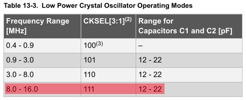
The above table gives the CKSEL[3:1] values as 111 but CKSEL0 value is missing. The other values can be found in the Crystal start up times table.
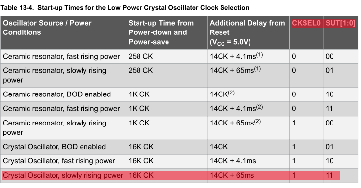
From which the values of CKSEL0 = 1 and SUT[1:0] =11.
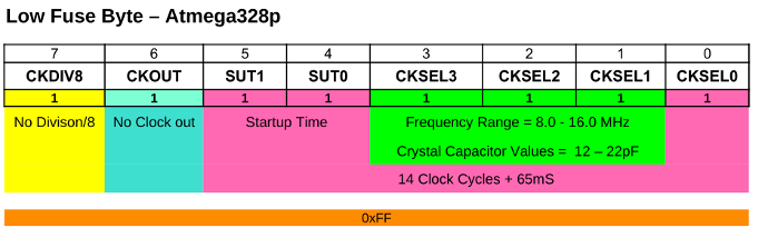
So Low Fuse byte value equals 0xFF.
Programming the Fuses of ATmega328p using AVRDUDE
After you have figured out the Low Fuse Byte value as 0xFF,You can program the Fuse bits of ATmega328p using AVRDUDE and a compatible programmer like USBasp or USBtinyISP.
Make sure that an External Crystal is attached to your Microcontroller.
Here we are using USBasp so programming command is as follows.
avrdude -c usbasp -p m328p -U lfuse:w:0xFF:m
Programming AVR Fuses using ATMEL Studio 7

Please note that ATMEL Studio 7 is now deprecated and is replaced with MPLAB X IDE. This section is for people who still use them.
Here we will use ATMEL Studio 7 and ATMEL ICE to set the fuses of ATmega328P microcontroller to the following specification.
11.0592MHz External Quartz Crystal with 22pF capacitors for Slow rising power
ATMEL Studio is an integrated development environment from Microchip Corporation (Formerly ATMEL).The IDE supports all the AVR microcontroller derivatives including the one with the ARM cores.
As a programming/ debugging tool ,we will be using the ATMEL ICE (AT ATMEL ICE) which is a powerful development tool for debugging and programming ARM® Cortex®-M based SAM and AVR microcontrollers with on-chip debug capability.
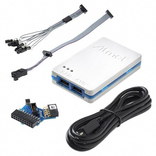
Connect the debugger/programmer ATMEL ICE to your PC using the micro USB capable provided.
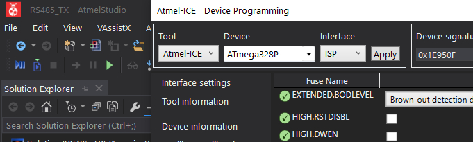
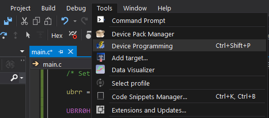
Now go to Tools → Device Programming in the menu bar as shown below.
After clicking on Device Programming, You will see the below window
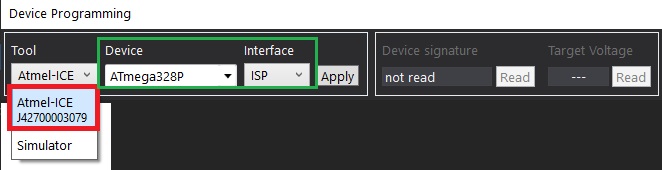
If your debugger/Programmer is detected, you can see the connected device under the Tool dropdown box.
- Select ATMEL-ICE in our case
- and Select ATmega328P from the Device drop down box.
- Select the Interface as ISP
and then press APPLY button.
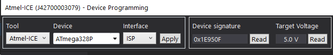
Now you can read the device signature of ATmega328p microcontroller in your development board by pressing Read button on the right hand side .
The window also shows the voltage of the microcontroller connected to the development board.
Please note that the programming will not happen if the voltage read by the IDE is low for eg 1.8V.
Now click on the Fuses on the Left Side of the Window and you will be presented with the available fuses on your AVR Microcontroller. The number and type of fuses will differ depending upon the type of the AVR microcontroller you are using.
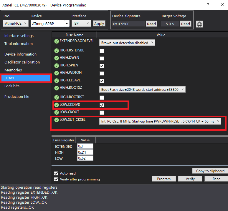
Here i am using an unprogrammed factory fresh ATmega328P microcontroller and in the below figure you can see the default settings of the fuses.
To get our desired fuse settings,
We will uncheck the LOW.CKDIV8 check box.(We do not want our clock to be divided/8)
and
Select External Crystal with startup time for 65mS in the LOW.SUT_CKSEL dropdown menu as shown below.
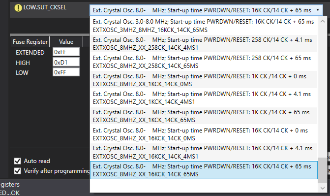
After you have made the above changes your settings window will look something like the below image.

We have only made changes to LOW.CKDIV8 and LOW.SUT_CKSEL settings.
Please note that the LOW Fuse Register is showing 0xFF .
Make sure that an External Crystal is attached to your Microcontroller before trying this.
Press Program Button to Set your Fuses.
You will be greeted by another warning message as shown below.
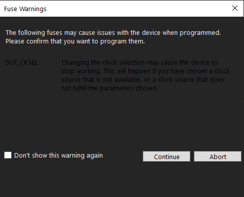
Press Continue to program the fuses.
Setting the F_CPU Value in ATmel Studio
F_CPU value is used to tell the frequency at which the microcontroller is running to the <util/delay.h> header file.
This value is used to calculate the delays when we use the functions like
- _delay_ms()
- _delay_us()
in our code.
F_CPU value is a way of telling the code which clock settings you have selected by setting the microcontroller fuses.
For Eg:
If you have connected a 4 MHz crystal to your ATMEL Controller and you have set F_CPU as 16MHz,
The Microcontroller will be running at 4Mhz but all your delay routines will be using the value of 16MHz for calculating their delay ,which will result in incorrect timings
In ATMEL Studio you have to use a #define statement to declare your F_CPU value ,Other wise you will receive a warning like this
Severity Code Description Project File Line
Warning #warning "F_CPU not defined for <util/delay.h>" [-Wcpp]
Code for Setting F_CPU value in ATMEL Studio
//Demo code to show F_CPU
#include <stdint.h>
#include <avr/io.h>
#define F_CPU 11059200 //Should be defined above #include <util/delay.h>
#include <util/delay.h>
int main(void)
{
char Your_Var = 0;
Your_Code_here();
}
Always define #define F_CPU 11059200 above #include <util/delay.h> header file other wise the util/delay.h will use the default value.
here CPU is running at 11.0592MHz so F_CPU 11059200 .
Configuring the System Clock Prescaler of ATmega328P
ATmega328 has a System clock Prescaler which can be used to scale down the clock frequency by a factor of 2 to 256.
This feature can be used to decrease the system clock frequency and the power consumption when the requirement for processing power is low
It is situated after the clock multiplexer block controlled by the Fuse Low byte register as shown in the below figure.

So in our case, The System Clock Prescaler will be a fed a 11.0592MHz signal by the Clock Multiplexer which can be divided by a factor of 2 ,4,8,18,32 up to 256
The Scaling factor is controlled by writing appropriate values to the CLKPR register bits.
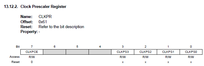
CLKPS[3:0] bits in the CLKPR controls the division factor

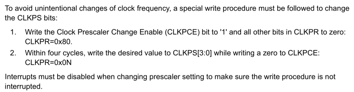
These bits can be written at run time provided a special write procedure is followed.(shown below)
The clock from the Prescaler is fed to other peripherals like CPU, ADC,IO Modules, Timers etc, adjusting the clock frequency will affect clocks to all other peripherals.
.
In our case we are dividing the clock by a factor of 1,
So CPU ,ADC, Timers, USART etc will be clocked using a 11.0592Mhz clock.
Once you have learned how to configure the clock sources and prescalar of ATmega328p,
You can now learn to communicate with a Linux/Windows/Mac using the ATmega328p USART(UART) in asynchronous mode.
Tags
- Log in to post comments